Choosing Antennas for Amateur Radio: A Practical Guide for Beginners

A typical amateur radio antenna installation. Source: Wikimedia Commons (CC BY-SA)
For a new amateur radio licensee in Poland, antenna selection is often the first significant practical decision. The antenna has a larger effect on station performance than almost any other component — a modest transceiver connected to a well-placed antenna will typically outperform a high-power radio connected to a poor one.
The options available depend heavily on the operating location: a flat in a Warsaw apartment block presents entirely different constraints from a house with a garden in rural Mazowsze or a suburban area in Śląsk.
The Half-Wave Dipole
The half-wave dipole is the fundamental antenna from which most other designs derive. It consists of two equal-length conductors fed at the centre, with each arm measuring one-quarter wavelength. For the 20-metre HF band (14 MHz), each arm is approximately 5.05 metres, making the total span about 10.1 metres.
The dipole is resonant at its design frequency, presenting a feedpoint impedance of approximately 70 ohms (slightly above the standard 50-ohm coaxial cable impedance). It can be fed directly with 50-ohm coax using a simple choke balun to prevent feedline radiation.
Advantages of the Dipole
- Simple to construct from readily available wire (copper or aluminium)
- No ground system required (unlike verticals)
- Predictable radiation pattern — broadside to the wire axis
- Low cost; the primary expense is quality coax and connectors
- Can be configured as an inverted-V when only one high support point is available
Practical Considerations in Polish Urban Areas
Apartment dwellers in Polish cities frequently face restrictions from building management (wspólnota mieszkaniowa) on external antenna installation. In these cases, a dipole can sometimes be installed in a loft space or run along a balcony railing as a compromise. Performance is reduced by proximity to building materials, but the antenna remains functional for local contacts and digital modes such as FT8 where signal levels matter less than for SSB voice.
In Poland, building regulations (Prawo budowlane) do not automatically prohibit amateur radio antennas, but building management rules vary. It is advisable to consult the wspólnota or spółdzielnia before installation. PZK can provide guidance on common situations.
Vertical Antennas
A quarter-wave vertical antenna is compact in the horizontal plane and radiates with a low-angle signal useful for DX work on HF. Its main trade-off compared to a dipole is the requirement for a ground system — radial wires laid on or just below the soil surface — to provide an effective return path for the antenna current.
UHF vertical antennas typical for repeater and fixed station use. Source: Wikimedia Commons (CC BY-SA)
For VHF and UHF operation, quarter-wave verticals are physically small. A 2-metre (144 MHz) quarter-wave vertical is approximately 51 cm. These antennas are commercially available and do not require an extensive ground system when mounted on a metallic surface (such as a car roof or a grounded aluminium plate), which acts as the counterpoise.
Ground Radials
An HF vertical without radials will work, but efficiency is significantly reduced. A practical starting point is 16 to 32 radial wires, each cut to a quarter-wavelength, laid on the ground surface and connected to the antenna base. The radials do not need to be buried in Polish soil conditions; lying on the surface provides nearly the same performance.
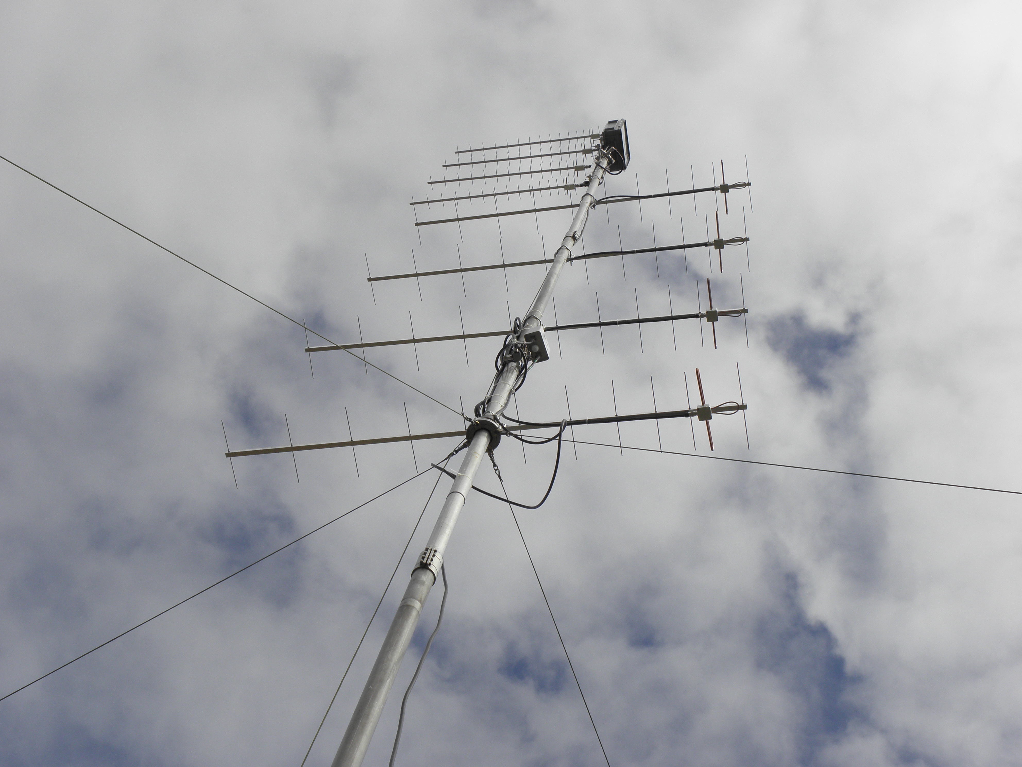
Yagi-Uda Directional Antennas
The Yagi-Uda antenna (commonly called a Yagi) uses a driven dipole element combined with passive reflector and director elements to concentrate RF energy in a single direction. A typical 3-element Yagi for the 20-metre band provides approximately 7–8 dBi of forward gain, which is roughly equivalent to tripling the effective transmitter power in the forward direction.
For Polish operators interested in VHF contesting or EME (moonbounce), stacked arrays of multiple Yagi antennas provide significant gain. Contest stations in the Polish countryside sometimes erect towers carrying 4-element Yagi stacks for 2 metres, achieving 16 dBi or more of gain.
Mechanical Considerations
Yagi antennas for HF are physically large. A 3-element 20-metre Yagi has a boom length of approximately 7 metres and requires a rotating mast and rotator. Polish wind loads must be considered — EN 1991-1-4 (wind actions standard) applies to antenna structures. A qualified structural assessment is advisable for masts taller than 3–4 metres.
Magnetic Loop Antennas
For operators in Polish city apartments where a full-size wire antenna is not possible, a small transmitting loop (magnetic loop) is a practical compromise for HF operation. A loop with a circumference of approximately one-tenth of a wavelength can be effective, though it is narrowband (requiring retuning for each frequency change) and sensitive to nearby objects.
Commercial magnetic loops are available, and home construction is well-documented in amateur literature. The primary challenge is the high voltage developed across the tuning capacitor at even modest power levels — appropriate safety precautions apply.
VHF/UHF Antennas for Local and Repeater Work
Category B licence holders, who are restricted to VHF and UHF bands, typically start with a simple collinear vertical antenna for the 2-metre or 70-centimetre band. These provide omnidirectional coverage at low elevation angles, which is optimal for working through repeaters (przekaźniki) in Poland's urban centres.

The Kenwood TS-590S, a popular HF transceiver used with various antenna configurations. Source: Wikimedia Commons (CC BY-SA)
The PZK maintains a database of active repeaters in Poland. Connecting to a local repeater with a handheld radio and a simple rubber duck antenna is usually the first practical operating experience for a new licensee.
Feed Lines and Connectors
Antenna performance is only as good as the feedline connecting it to the transceiver. RG-213 coaxial cable (low-loss 50-ohm) is a standard choice for HF runs up to 30 metres. For longer runs or VHF/UHF frequencies, low-loss alternatives such as LMR-400 or Ecoflex-10 reduce signal loss significantly. PL-259 (UHF) connectors are the most common in amateur HF equipment; N-type connectors are preferred at VHF/UHF for lower loss.